Student guide
Wire the three boards, see a card move on the live graph, then measure the travel of your own tabletop sash.
Print the one-sheet guide (PDF)
Wire the kit with USB unplugged
Leave the ESP32 beside the breadboard so its pins are accessible. Each bag corresponds to a lettered column. Push the socket end of each lead onto the printed pin label and the pin end into its breadboard hole. Holes a–e connect across one numbered row.
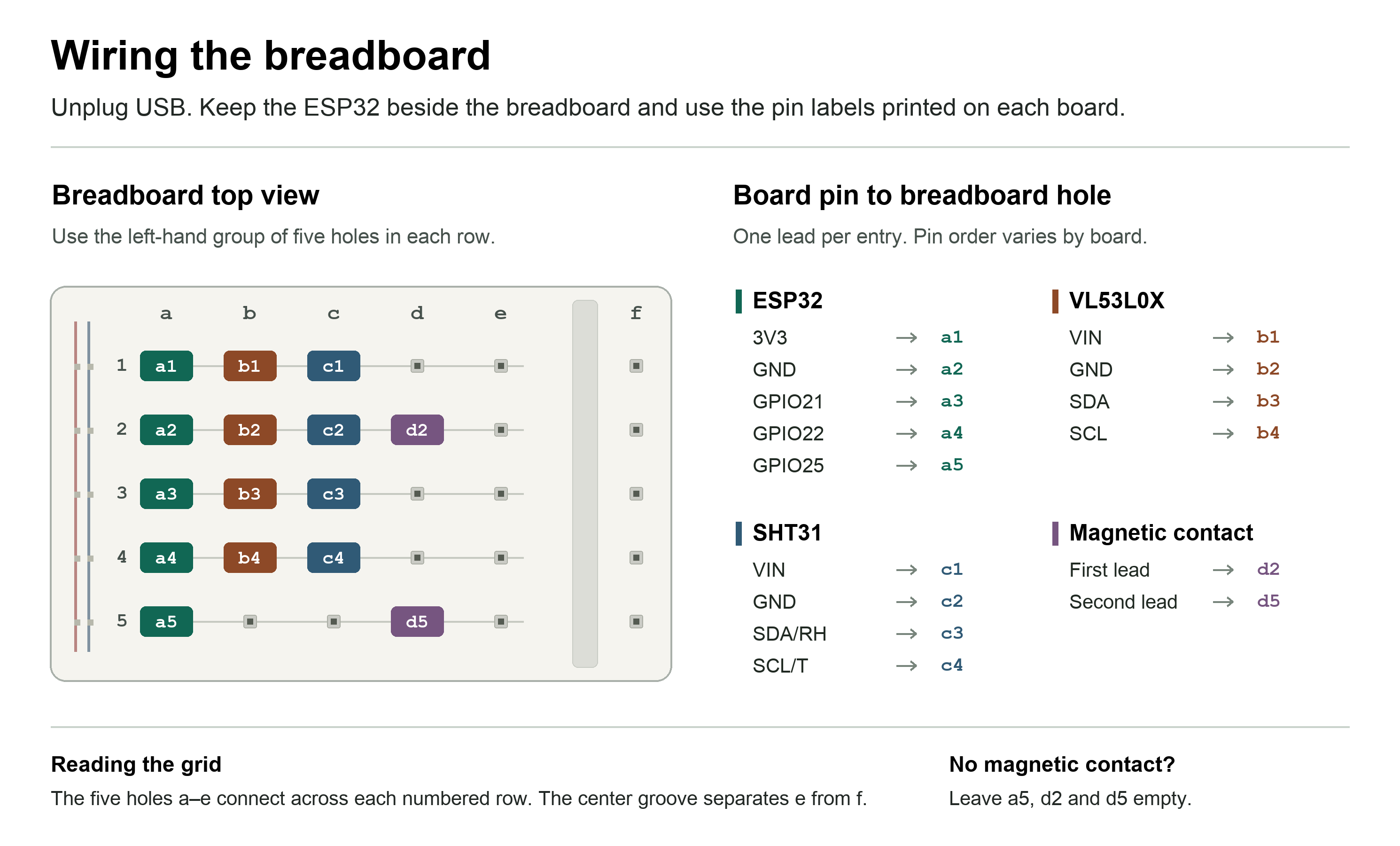
| Row | Bag 1 ESP32 | Bag 2 VL53L0X | Bag 3 SHT31 | Magnetic contact |
|---|---|---|---|---|
| 1 | 3V3 → a1 | VIN → b1 | VIN → c1 | — |
| 2 | GND → a2 | GND → b2 | GND → c2 | Lead 1 → d2 |
| 3 | GPIO21 → a3 | SDA → b3 | SDA/RH → c3 | — |
| 4 | GPIO22 → a4 | SCL → b4 | SCL/T → c4 | — |
| 5 | GPIO25 → a5 | — | — | Lead 2 → d5 |
Trace the three power wires across row 1 to 3V3 and the grounds across row 2 to GND. The range sensor and SHT31 each have four connections. Either magnetic-contact wire can go to ground. If the switch is absent, leave a5, d2 and d5 empty.
Get a moving graph with a card
- On a laptop using desktop Chrome or Edge, open sashsense.mosherpa.org/kit. Plug the wired board into that laptop with the USB data cable. A “Firmware loaded and checked” sticker means you can go straight to the graph without installing Arduino. No account or download is needed.
- Close Arduino Serial Monitor and Serial Plotter if either is open. Click Connect kit and allow the board’s serial port. Look for CP210x, USB-to-UART, or an ESP32 entry. If several ports appear, cancel, unplug the kit and compare the list. Reconnect and select the port that reappears.
- Hold a matte card squarely in front of the small optical window on the VL53L0X, about 20 cm away. Move it toward the sensor and back. On the Distance graph, millimeters should fall as the card approaches and rise as you pull it back. You can run this check before building any stand.
Measure a known movement
Fix the range sensor above a flat, matte target. A clamp and sliding card, a book-supported stand, or scrap packaging works. Keep the surface in view for 10 cm of travel toward the sensor. If using the contact, attach its wired half to the stand and its magnet to the target so they meet at closure.
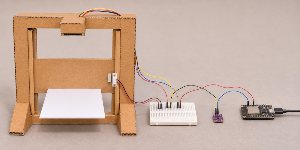
- Hold the target at its closed position and click Set zero. The graph changes to sash opening when the board confirms. If you connected the switch, select Switch fitted.
- Mark an edge at zero. Move that edge 5 cm and then 10 cm toward the sensor. Pause at each ruler mark. Opening should increase and raw distance should decrease. Close five times and record the range of closed readings.
- Click Export CSV before reloading or closing the tab. The latest 3,600 readings stay in this browser tab. Re-zero after resetting the board or moving the mount.
This tabletop kit measures movement, temperature and humidity. Use it for bench experiments; its readings cannot establish fume hood containment.
If readings do not appear
Temperature changes but distance is blank. The kit is connected. Center a matte card over the VL53L0X and clear its optical window. If the range is still blank, unplug USB and check bag 2’s VIN, GND, SDA and SCL at b1–b4. Reconnect and try the card again.
No port or busy port. Use the USB-connected laptop in desktop Chrome or Edge. Close other tabs or apps holding the board. Try a known data cable and reconnect. Ask your instructor if a campus laptop blocks serial access.
Connected but no measurements. Check the board’s firmware sticker or ask your instructor to try a checked kit. For a blank board, follow the setup below.
One-time firmware setup
Use this section for a blank board or when changing the starter program. Disconnect the live graph before uploading.
- Download the starter sketch (.ino) and open it in Arduino IDE. Accept the prompt to place it in a folder named SashSense_Developer. A foldered ZIP is also available.
- In IDE settings add
https://espressif.github.io/arduino-esp32/package_esp32_index.jsonunder Additional Boards Manager URLs. In Boards Manager install esp32 by Espressif Systems. - In Library Manager install Adafruit VL53L0X and Adafruit SHT31 Library, including their dependencies. Select ESP32 Dev Module and its USB port. Click Upload.
- Close any serial monitors and return to the live USB graph.
For instructors
Before class, try a prepared kit and its data cable on a campus laptop using a student account on the computer. Confirm the USB port chooser opens and the graph responds to a card. Apply the firmware check label only after verifying the kit.
During the pilot, time the first team from opening the box to seeing the line move. Note where they first ask for help and whether they can export their CSV independently.